Modifications For The Dynaco™ ST-70 Basic Amplifier
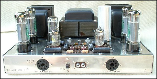
Stock amplifier shown. (I no longer have pix of a modified amp!)
Note: This information is provided for personal use only. All information and design remains the property of KTA/Kevin Kennedy and may not be used for commercial purposes without permission. Licensing for commercial use available upon request.
The modifications detailed here really amount to a virtually complete gut job on this amplifier. Only the transformers, chassis, and cage are retained.. If you are like most, you will probably wonder why someone would develop yet another driver circuit for the venerable Dyna ST-70. The reasons are numerous, but not the least of which is the widespread availability of this amplifier at a reasonable price, and the good quality of the output transformers.
The ST-70 represents a very desirable package for the modifier as it lends itself to a large number of modifications from the most simple to the most complex, witness the AR ST-70-C3 that graced the pages of the Audio Amateur about 20 years ago. This modification is rather less complex, but is capable of exceptional performance nonetheless.
The new driver circuitry is fairly uncritical in terms of its layout and lends itself well to pcb, perf board or point to point wiring, but very high voltages will be present in operation, so exercise caution in the construction, debugging, and operation of this amplifier.
If you have not yet purchased a Stereo-70 to modify you want to look for one equipped with the A470 output transformers, as models with the later Z326 (Japanese) transformers may not sound as good. The part number can be found stamped on the transformer end bell facing towards the output tubes, and you can also tell by whether or not the output transformers have cloth insulation on their wiring, the Z326 has plastic insulated wires. In addition the earlier PA060 power transformer is considerably larger and runs somewhat cooler.
GENERAL DESCRIPTION
This design encompasses improvements in a number of areas besides the obvious changes in driver circuitry. Linearity in the output stage is a crucial issue to the overall sound of an amplifier, and for this reason I highly recommend triode output operation unless you really need the additional output power. The amplifier may be wired for ultra-linear or triode mode operation or alternatively switches may be installed allowing instant selection of either mode.
Operating the 6CA7/EL34 output tubes in triode mode results in very low plate resistance as compared to pentode or ultra-linear operation as well as very little harmonic distortion beyond the second harmonic. Low plate resistance results in less phase shift in the output transformer, and better power bandwidth in the output stage. Power sensitivity is reduced by about 6dB, and power output is reduced to 16 watts RMS.
Examining the circuit diagram you will notice the absence of the original "Biaset" circuitry as well as the presence of several resistors in the cathode circuits of all three stages. These resistors are important to the design of the amplifier and should not be left out. They provide a limited amount of current feed-back to linearize the individual stages. The effect of this current feed-back is quite audible even in the output stages, and results in a cleaner, more detailed and relaxed (unstrained) sound.
POWER SUPPLY
The new power supply is infact identical in most respects to the old except in the area of supply decoupling on the driver board, refer to the driver schematic for the values. (R20 and R22 are located on the Quad cap as in the original circuit.) The bias supply topology is unchanged except that a silicon diode should be substituted for the original selenium stack, and larger values of electrolytic capacitor can be employed in the supply. Use 100V parts here.
Some of you may want to utilize solid state rectifiers, although I don't recommend this - in place of the 5AR4 rectifier, but if you elect to do this you must use capacitors with a voltage rating in excess of 600 volts, or series connect two capacitors of 300 volt rating or better with voltage sharing/bleeder resistors in parallel in place of each of the individual capacitors. The unused 5 volt winding could then be used to drive a full wave voltage doubler, in turn supplying a LM317 wired to provide 6.3 vdc to the input tube filaments....
DRIVER CIRCUITRY
The driver circuitry is relatively straight forward and may be built on perf board. The design consists of a single 12AX7A used as voltage amplifier shared between both channels, driving a pair of 12AU7A's connected as cathode coupled inverters. See schematic.
Use of current feedback in amplifier stages has the effect of reducing the stage transconductance resulting in higher slew-rates, higher bandwidth and in addition lower distortion in a given amplifier stage. It may also be used to control the overall gain in a stage. I prefer to use this type of feedback when possible in place of or in conjunction with limited global feedback.
The input stage provides an open loop gain of about 50, while the cathode coupled phase splitter provides a gain of about 5-6 for an overall gain of between 250-300. (approx. 48dB) Open loop bandwidth is well in excess of 50KHz prior to loop compensation. Closed loop gain is approx. 27dB and the input impedance is 100K ohms.
FEEDBACK
The overall loop feed-back is quite low at approximately 20dB, but in this application global feedback confers some advantages in the areas of distortion reduction, lowered output impedance (increased damping factor) and most importantly reduces voltage output dependance on load impedance.
I feel that high levels of global feedback may make a device measure better, but is ill advised in many applications because interstage delays result in a delayed feedback signal which causes smeared transient response and a loss of detail. Further, although global feedack may result in a reduction of harmonic distortion, it also results in additional small quantities of higher order harmonic distortion products.
Tube power amplifiers generally utilize fairly low levels of global feed-back because output transformer phase shift at the frequency extremes can cause oscillation if excessive feedback is employed, and in addition high feedback levels usually require rather severe loop compensation to assure that gain is less than unity at the point at which phase shift becomes 180 degrees. Failure to adhere to these criteria usually results in an oscillator.... I try to design circuits with fairly constant feed-back margins in the audio pass band, but this does imply careful control of gain across the audio bandwidth because excessive gain levels require progressively earlier roll-off of the voltage amplifier stages in order to prevent oscillation at one frequency extreme or the other...
"The one last thing you need to know is the impedance of your loudspeaker because in some situations performance will be enhanced by taking the feedback from the actual tap in use rather than from the more traditional 16 ohm taps." Edit 2007.01.23: I no longer recommend this, and instead suggest always using the 16 ohm tap of the A470 for feedback. I have noticed a definite difference in sound quality in favor of the 16 ohm tap regardless of the actual tap the speaker load is connected to. This may or may not apply to non-Dynaco transformers so I advise experimenting. In the case where you have a transformer with 4.3K primaries and only 4 or 8 ohm taps use 499 ohms or 715 ohms respectively. Note that the values of compensation components C1 and R6 may need slight adjustments for best squarewave response at 10kHz.
Edit 2007.01.23: Improved compensation values for C1 and R6 based on feedback from a builder planning to use the amplifier primarily in UL connection. These values are also recommended for use with triode connection.
CONSTRUCTION
Start by completely gutting the candidate amplifier, except for the transformers and the associated AC power wiring. You should probably start by replacing all the tube sockets with new ones purchased from Sound Values or your favorite broker. I would recommend replacing the quad cap with a new one, or better still with one having three or four sections of 40uF at 500 volts or better. You can also build out the capacitors with the diminutive Panasonic snap mount types. The bias pots are best replaced by components of equal value. (Ohmite makes a very nice mil spec locking pot that can be had for much less than $10.00 each. Check Digikey catalog.)
The old input jacks and output terminals should be replaced with something better. I favor the Edison Price MusicPost™ for the outputs and Vampire™jacks for the input. Be certain to mount the input jacks so that they are isolated from the chassis. Remove the old octal sockets on the front apron and replace with pcb material drill to accept a pair of pin jacks or similar..
Depending on condition consider replacing the octal sockets for the rectifier, and output tubes.
Now you should have a chassis that is basically empty, and ready for the construction of the new amplifier. As I no longer have a pcb available for this modification you can either layout the circuit on a pcb, or build it on Vector Board™. Building on vector board is quite easy. I recommend that the board be sized very carefully to the existing opening, and that boundaries be marked. The socket for the 12AX7A should centered, but slightly forward towards the rca jacks, the sockets for the 12AU7A's should be symettrically placed about 1/4th of the way in from the edges at either end. Allow room for the coupling caps to the EL34's by each 12AU7A, and for the grid rtn caps nearby. (Place in a C around the 12AU7A's.)
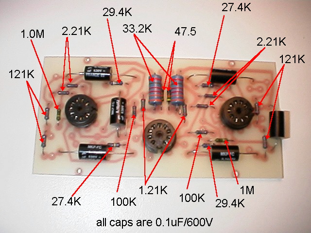
I constructed my prototype on perf board and have had no reliability problems at all. The power supply I elected to use is basically similar to the stock supply with the exception that it has higher capacitance than when it was stock. I used metal film resistors from Dale, IRC and Resista, the coupling caps are CDE WMF series parts which I recommend highly, although some of you may object to them I find them to be quite good, and one of the few that will fit (barely) in the space available, but if you feel inclined, bypassing them with 0.01uF MIT Caps would be a nice enhancement...
I mounted conventional chassis mount tube sockets on the perf board upon which I built my prototype. Almost all of the parts were mounted on the board, but clearance is a little tight. The 12AX7A should be mounted near the input sockets and the two 12AU7A's were mounted centered about one inch from the edge closest to their respective output tubes. To avoid the possibility of ground loops, only one point should be grounded to the chassis. In addition the input grounds and feed-back grounds should be one and the same for their respective channel.
Edit: I strongly recommend better quality coupling caps than fitted in the old kit boards. Caps by REL or Clarity Cap are recommended.
TUBES
I recommend the Tungsram 12AU7A for the cathode coupled phase inverter circuit and a Sovtek 12AX7WXT+ for the input stage. I use vintage Mullard EL34 matched pairs in the output stages and an Amperex 5AR4 rectifier in the power supply.
Edit 2007.01.23 Current production JJ 12AX7A, 12AU7A, and EL34 sound great in this design. The EH EL34 is another well liked type. I recommend all power tubes be burned in and matched for at least 24 hours prior to purchase. Don't buy untested, unmatched tubes for this or any amplifier project - this one thing will save you a lot of grief. Removed reference to ersatz 5AR4 as I doubt this is a problem any longer. Use a reputable current production tube from JJ, or Shuguang. To improve reliability and longevity install a single diode (HF4007 or eq.) in series with each plate (banded end connected to socket) which will reduce or prevent the occasional arc during warm up or under transient conditions.
THE SOUND
I have never been impressed with the performance of any of the several Dynaco tube amplifiers I have owned, having owned McIntosh MC-30's, a H&K Citation II and assorted other tube power amplifiers, against which to compare them, but I am impressed with the performance of this one. This amplifier is detailed, clean, and open, with good depth and imaging. Performance is excellent to both frequency extremes, with a very sweet, but not euphonic mid-range. Voices and piano are reproduced with great realism and clarity. The amplifier is overall very neutral and detailed without the stridency present in many other amplifiers sharing these virtues.
Page Maintenance Policy (New)
This page is regularly updated and maintained. Several hundred of these amplifiers have been built by enthusiasts from scratch as well as from the board kit I used to sell.
I would like to note that the way I develop circuits has evolved quite a lot in the 17yrs since I designed the mod and wrote this article. This represents one of my earliest serious efforts at attaining better tube sound and is a reflection of what I knew at the time. It has also been one of my greatest long term successes, people are still building the original design today.
©1989, 1994, 1998, 2001, 2007 By Kevin R. Kennedy