This project is not recommended for the first time constructor. This amplifier design utilizes high voltages which can be extremely hazardous to the inexperienced constructor.
A pushpull pair will produce approximately 9Wrms on sinewave testing, and a peak value on music of up to 14Wrms before the onset of clipping. Two 6189/12AU7 are used in a novel cross coupled, self balancing driver circuit. No loop feedback is used. Full power output is maintained out to 30KHz. Overall voltage gain is quite low at 14dB due to the low mu tubes chosen for the application.
Component Quality Due to the absence of global feedback the quality of components is quite audible, therefore I recommend Holco(low voltage points only), Resista or Caddock resistors and MIT caps - also some TRW polystyrenes are good sounding. I used vampire jacks, and Cardas wire in mine.
The power supply must be built on a separate chassis as the amplifier has virtually no immunity to external magnetic fields due to the absence of global feedback. The amplifier has about 40dB of supply rejection at 120Hz, so virtually all of the ripple in the supply should be filtered out. The suggested power supply will result in unmeasurable hum at the output. (Less than 1mVrms, typically 100uVrms or less.)
You can use an LM317 or a LM7812 with a 1N4003 in series with the ground terminal. (so that
the diode is forward biased.) Use a transformer with a secondary rating of 18V@1A, feeding a
bridge rectifier, a 10,000uF filter cap, and at least 2200uF on the output.
Note: This amplifier can be easily modified for balanced inputs (XLR) and will provide 20dB of voltage gain.
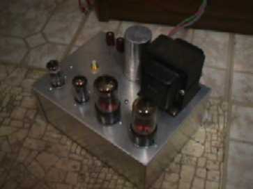
Complete6CK4 Amplifier Schematic
This file contains both the power supply schematic and the amplifier schematic in unrestricted/printable pdf format. 11/27/2005